- 您现在的位置:买卖IC网 > Sheet目录19092 > DT900020 (Red Lion Controls)RATE INDICATOR ADJ RED BACKLIGHT
�� �
�
�INSTALLATION� ENVIRONMENT�
�The� unit� should� be� installed� in� a� location� that� does� not� exceed� the� maximum�
�operating� temperature� and� provides� good� air� circulation.� Placing� the� unit� near�
�devices� that� generate� excessive� heat� should� be� avoided.�
�The� bezel� should� be� cleaned� only� with� a� soft� cloth� and� neutral� soap� product.�
�Do� NOT� use� solvents.� Continuous� exposure� to� direct� sunlight� may� accelerate�
�the� aging� process� of� the� bezel.�
�PROGRAMMING� MENU�
�Note:� The� display� changes� on� “PAR”� or� “SEL”� push� button� release.�
�PROGRAMMING�
�From� the� factory,� the� Ditak� 9� is� programmed� with� a� fixed� 1� second� timebase�
�to� read� directly� in� HZ� or� RPM� with� a� 60� tooth� gear� To� enter� the� programming�
�mode,� place� a� jumper� between� the� Push� Button� Enable� (P.� B.� En.)� Terminal� and�
�the� Common� Terminal.� Once� the� jumper� is� connected� the� programming� buttons�
�are� now� activated.� The� Programming� Mode� consists� of� three� selections;� Rate�
�Multiplier,� Decimal� Point,� and� Timebase.� There� is� a� fourth� display� which� is� the�
�main� display� or� run� mode.� Once� programming� is� complete,� the� unit� must� be�
�returned� to� the� main� display� before� exiting� the� programming� mode� to� obtain�
�normal� operation.�
�3�
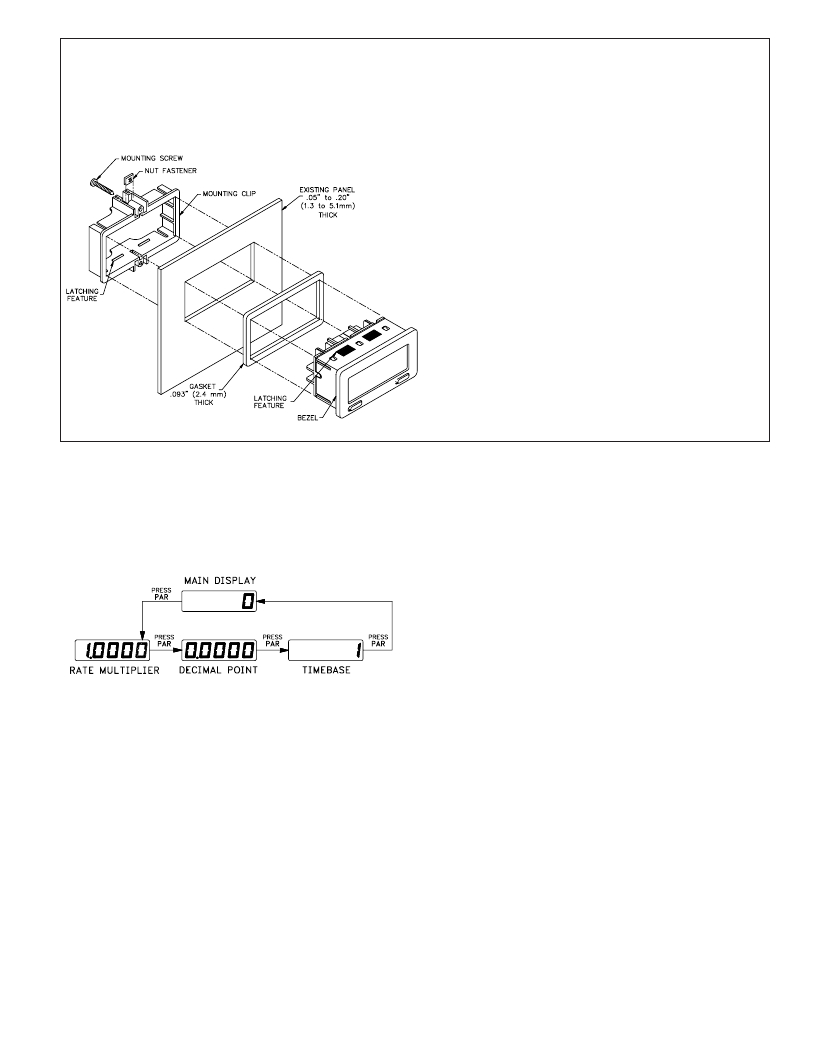
�INSTALLATION�
�The� Ditak� 9� meets� NEMA� 4X/IP65� requirements� for� indoor� use,� when�
�properly� installed.� The� units� are� intended� to� be� mounted� into� an� enclosed�
�panel.� A� sponge� rubber� gasket,� mounting� clip,� two� screws,� and� nut� fasteners�
�are� provided� to� install� and� seal� the� unit� in� the� panel� cut-out.�
�The� following� procedure� assures� proper� installation:�
�1.� Cut� panel� opening� to� specified� dimensions.� Remove� burrs� and� clean� panel�
�opening.�
�2.� Slide� the� panel� gasket� over� the� rear� of� the� unit� to� the� back� of� the� bezel.�
�3.� Slide� nut� fastener� into� slot� on� mounting� clip� and� then� insert� mounting� screw�
�through� nut� on� both� sides� of� mounting� clip.� Tip� of� mounting� screw� should�
�NOT� project� through� hole� on� clip.�
�4.� Install� Ditak� unit� through� panel� cut-out.�
�5.� Slide� mounting� clip� over� rear� of� unit� until� clip� is� against� back� of� panel.� The�
�mounting� clip� and� Ditak� housing� have� a� latching� feature� to� hold� the� unit� in�
�place� until� tightened.�
�Note:� Hold� the� Ditak� front� bezel� in� place� when� sliding� the� mounting� clip�
�into� position.�
�6.� Alternately� tighten� each� mounting� screw� to� ensure� uniform� gasket� pressure.�
�Visually� inspect� the� gasket� for� proper� seal.� The� gasket� should� be�
�compressed� approximately� 75� to� 80%� of� its� original� thickness.�
�7.� If� the� gasket� is� not� adequately� compressed� and� the� mounting� screws� cannot�
�be� tightened� any� further,� loosen� mounting� screws� and� insure� that� the� clip� is�
�latched� as� close� as� possible� to� the� panel.�
�8.� Repeat� step� #6� for� tightening� the� mounting� screws.�
�RATE� MULTIPLIER�
�The� Ditak� 9� has� a� Rate� Multiplier� (RM)� selection� range� from� 0.0001� to�
�1.9999.� See� Programming� Calculations� to� determine� the� calculated� value.� After�
�entering� the� programming� mode,� the� least� significant� digit� will� be� flashing.� To�
�increment� this� digit,� press� the� SEL� button.� After� the� value� 9,� the� digit� will� start�
�over� at� 0.� To� move� to� the� next� digit� press� PAR� and� then� that� digit� can� be� changed�
�by� pressing� SEL� .� When� reaching� the� most� significant� digit,� pressing� PAR� will�
�advance� the� meter� to� the� Decimal� Point� selection.�
�DECIMAL� POINT� SELECTION�
�The� selection� of� the� decimal� point� position� for� the� display� (DDP)� is�
�accomplished� by� repeatedly� pressing� SEL� .� This� selection� will� always� default� to�
�0.0000� when� advancing� to� it� from� the� Rate� Multiplier� selection.� By� pressing�
�PAR� ,� the� shown� decimal� point� selection� is� entered� and� the� Time� base� selection�
�is� shown.�
�TIMEBASE� SELECTION�
�The� Ditak� 9� has� a� Time� Base� selection� range� from� 1� second� to� 7� seconds.� See�
�Programming� Calculations� to� determine� the� calculated� Rounded� Time� Base�
�(RTB)� value.� The� value� is� changed� by� pressing� SEL� .� The� value� is� entered� by�
�pressing� PAR� and� the� Main� Display/Run� Mode� is� shown.�
�Note:� The� position� of� the� decimal� point� has� no� effect� on� this� selection.�
�MAIN� DISPLAY/RUN� MODE�
�This� display� follows� the� Timebase� Selection.� The� unit� must� be� in� this� mode� to�
�exit� the� Programming� Mode� and� have� the� unit� display� properly.� The� push� button�
�enable� jumper� can� be� removed� after� the� Ditak� 9� is� returned� to� the� main� display.�
�发布紧急采购,3分钟左右您将得到回复。
相关PDF资料
550-5304
LED 5MM VERT SUP DIFF YEL PC MNT
550-5207
LED 5MM RT ANG SUP DIFF GRN PCMT
550-5204
LED 5MM VERT SUP DIFF GREEN PCMT
550-5107
LED 5MM RT ANG SUP DIFF RED PCMN
CUB7W010
COUNTER 8-DIGIT YEL BKLT VOLT-IN
CUB7W000
COUNTER 8-DIGIT REFLECT VOLT-IN
550-2504
LED 5MM VERT HI EFF ORANGE PCMNT
550-2407
LED 5MM RT ANG HI EFF RED PCMNT
相关代理商/技术参数
DT-900-3
制造商:Nidec-Shimpo America Corporation 功能描述:REPLACEMENT LENS FOR MODEL DT-900
DT900-4
制造商:Nidec-Shimpo America Corporation 功能描述:REPLACEMENT HANDLE PAD FOR MODEL DT-900
DT-900-PR
制造商:Nidec-Shimpo America Corporation 功能描述:STROBOSCOPE, 40FPM TO 12500FPM, 0.01%; Flash Rate Range:40FPM to 12500FPM; Accuracy %:0.01%; Supply Voltage V AC:115V; Flash Rate Max (FPM):12500; Stroboscope Features:Phase Shift and Rate Multiplier/Divider ;RoHS Compliant: NA
DT9150
制造商:未知厂家 制造商全称:未知厂家 功能描述:Interface Daughter Card
DT9281-QZ
制造商:DEWALT 功能描述:63PC ACCESSORY SET
DT9282-QZ
制造商:DEWALT 功能描述:57PC ACCESSORY SET
DT9296-QZ
制造商:DEWALT 功能描述:DRILL BIT SET 90PC
DT92N10KOF
制造商:n/a 功能描述:Power Module